Atmospheric Inlet - SimFlow (OpenFOAM) Description
Atmospheric Inlet is a specialised boundary condition for prescribing an atmospheric boundary-layer (ABL) inflow, primarily in Computational Fluid Dynamics (CFD) simulations of environmental and meteorological flows.
The ABL occupies the lowest part of the troposphere, where surface effects dominate. In CFD, we often need fully developed velocity and turbulence profiles at the inlet to reproduce this layer faithfully.
Typical use-cases include:
- wind-comfort assessments
- external aerodynamics of vehicles, buildings or urban layouts
- any situation in which a realistic, equilibrium ABL inflow is required
Atmospheric Inlet - SimFlow (OpenFOAM) Understanding Atmospheric Inlet
The Atmospheric Inlet boundary condition imposes log-law, ground-normal profiles for velocity and turbulence quantities in a homogeneous, two-dimensional, dry-air, neutral and equilibrium ABL.
It can be applied to the velocity field and to turbulence variables \(k\), \(\epsilon\) and \(\omega\):
- ground-normal streamwise flow speed profile
\(u = \frac{u^{*}}{\kappa} \cdot ln( \frac{z - d + z_0}{z_0})\)
\(v=w=0\)
- ground-normal turbulent kinetic energy profile
\(k = \frac{(u^{*})^2}{\sqrt{(C_{\mu})}} \cdot \sqrt{C_1 ln(\frac{z - d + z_0}{z_0}) + C_2}\)
- ground-normal turbulent kinetic energy dissipation rate
\(\epsilon = \frac{(u^{*})^3}{\kappa (z - d + z_0)} \cdot \sqrt{C_1 ln(\frac{z - d + z_0}{z_0}) + C_2}\)
- ground-normal specific dissipation rate
\(\omega = \frac{u^{*}}{\kappa \sqrt{C_{\mu}}} \cdot \frac{1}{z - d + z_0}\)
- ground-normal friction velocity
\(u^{*} = \frac{u_{ref} \kappa}{ln(\frac{z_{ref}+z_0}{z_0})}\)
- \(u\) - ground-normal streamwise flow speed profile \([m/s]\)
- \(v\) - spanwise flow speed profile \([m/s]\)
- \(w\) - ground-normal flow speed \([m/s]\)
- \(k\) - Ground-normal turbulent kinetic energy (TKE) profile \([m^2/s^2]\)
- \(\epsilon\) - Ground-normal turbulent kinetic energy (TKE) dissipation rateprofile \([m^2/s^3]\)
- \(\omega\) - Ground-normal specific dissipation rate profile \([m^2/s^3]\)
- \(u^{*}\) - friction velocity \([m/s]\)
- \(\kappa\) - von Karman constant [-]
- \(C_\mu\) - model constant [-]
- \(z\) - Ground-normal coordinate component [m]
- \(d\) - Ground-normal displacement height [m]
- \(z_0\) - Aerodynamic roughness length [m]
- \(u_{ref}\) - Reference mean streamwise wind speed at \(z_{ref}\) [m/s]
- \(z_{ref}\) - Reference height being used in \(u^{∗}\) estimations [m]
- \(C_1\) - curve fitting coefficient for profiles [-]
- \(C_2\) - curve fitting coefficient for profiles [-]
Atmospheric Inlet - SimFlow (OpenFOAM) Application & Physical Interpretation
Atmospheric Inlet is used whenever the domain’s upstream boundary should deliver a fully-developed, neutral atmospheric boundary layer, e.g. wind-comfort studies around buildings, pollutant dispersion over terrain, or vehicle aerodynamics in a cross-wind. Instead of letting the flow build up inside the mesh (which is slow and mesh-dependent), the correct log-law velocity profile is prescribed, matching turbulence levels right at the inlet, so the solution downstream starts from physically realistic wind conditions.
Atmospheric Inlet in Wind Turbine Analysis applications
These types of simulations can be solved using the simpleFoam (solver). The goal is to analyze the airflow around wind turbines, including wake effects and optimal turbine placement in a wind farm.
| Physics | Pressure | Velocity |
|---|---|---|
Inlet | Zero Gradient | Atmospheric Inlet |
Outlet | Uniform Fixed Value | Inlet Outlet |
| Tutorial | Description |
|---|---|
Tutorial on simulating wind flow around buildings using an Atmospheric Inlet to model realistic wind profiles and evaluate effects on pedestrians and structures. | |
Validation case of SimFlow. Wind comfort around a single and cluster of buildings is investigated and compared to experimental data. |
Atmospheric Inlet - SimFlow (OpenFOAM) Atmospheric Inlet in SimFlow
To define Atmospheric Inlet in SimFlow in the boundary condition tap, for velocity or turbulent properties the proper option must be selected from the drop-down menu - Figure 1.
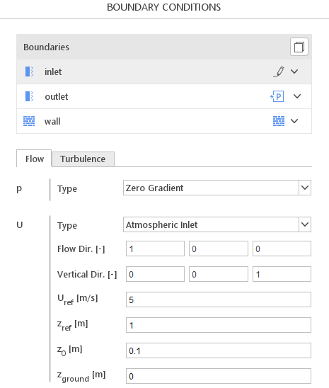
The following parameters must be defined:
Flow Dir. - direction of the air flow
Vertical Dir. - vertical direction (perpendicular to the ground)
\(U_{ref}\) - reference velocity
\(z_{ref}\) - reference height
\(z_{0}\) - roughness height
\(z_{ground}\) - ground location
Atmospheric Inlet - SimFlow (OpenFOAM) Atmospheric Inlet - Alternatives
In this section, we propose boundary conditions that are alternative to Atmospheric Inlet. While they may fulfill similar purposes, they might be better suited for a specific application and provide a better approximation of physical world conditions.
| Boundary Condition | Description |
|---|---|
adjusts the extrapolated velocity field perpendicular to the patch to match specified flow rates, with input values expressed in terms of mass or volumetric flow rate | |
sets a uniform value across the entire boundary, either constant or time-dependent |