Fan - SimFlow (OpenFOAM) Description
Fan represents an inlet or outlet total pressure condition that imposes a pressure jump, simulating the pressure difference generated by a fan. It does not simulate the physical rotation of fan blades; instead, it mimics the fan’s effect on the fluid flow by enforcing a pressure difference across a boundary patch in the mesh.
This approach offers a simplified way to model fan behavior, significantly reducing computational cost by avoiding the need to mesh and simulate detailed fan geometry. The boundary condition can be applied to both inlets and outlets of the computational domain, depending on the desired flow direction.
This boundary condition is typically used in internal flow simulations, such as HVAC systems, electronics cooling, ventilation ducts, or automotive under-hood airflow, where a fan contributes to the pressure distribution in a duct or enclosed system.
Fan - SimFlow (OpenFOAM) Understanding Fan
The Fan boundary condition models a pressure jump across a fan, which can be specified as a function of the flow rate. This boundary condition is particularly useful for simulating fans in duct systems, HVAC applications, and other scenarios where a fan induces a pressure difference.
The Fan boundary condition works as Total Pressure. It means that in reality, the static pressure is assigned to the boundary \(p_p\), based on the following equation:
- \(p_p\) - static pressure at the patch
- \(p_0\) - total pressure at the patch
- \(p_d\) - pressure drop
The pressure drop can be defined as:
- constant
\(\Delta p = \text{constant}\) - tabulated - a user-provided table of pressure jump versus volumetric flow rate, allowing for complex fan performance characteristics to be modeled.
The advantages of Fan are its simplicity, computational efficiency, and the stability of the solution. However, if detailed flow behavior around the fan blades, acoustic characteristics, or precise fan performance under varying operating conditions are important, a more comprehensive approach — such as the Multiple Reference Frame (MRF) or Sliding Mesh method — may be required. These methods incorporate the actual fan geometry into the computational domain, allowing for a more physically accurate simulation.
Fan - SimFlow (OpenFOAM) Application & Physical Interpretation
The Fan boundary condition is used to simulate a pressure jump across a fan surface — ideal for cases where detailed modeling of fan blades is not needed, but the net effect of the fan on pressure and flow must be included.
Fan in HVAC applications
Example applications: duct fans, exhaust fans, AHU (air handling units), building ventilation, server room cooling,clean room ventilation
This problem can be addressed using the buoyantSimpleFoam (solver). Fans drive flow through complex duct networks, balancing supply and return paths with pressure differences.
| Physics | Pressure | Velocity |
|---|---|---|
Inlet | Fan | Pressure Inlet-Outlet Velocity |
Outlet | Fixed Value | Inlet-Outlet |
Fan in Automotive applications
Example applications: radiator fans, cabin ventilation, engine bay cooling, underhood airflow, battery pack thermal management
This problem can be addressed using the simpleFoam (solver). The fan causes a pressure rise, pulling or pushing air through components like radiators, batteries, or vents.
| Physics | Pressure | Velocity |
|---|---|---|
Inlet | Fan | Pressure Inlet-Outlet Velocity |
Outlet | Fixed Value | Inlet-Outlet |
Fan - SimFlow (OpenFOAM) Fan in SimFlow
To define Fan on the domain’s boundary, the proper option must be selected from the drop-down menu for pressure in Boundary Conditions tab - Figure 1
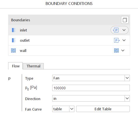
\(p_{0}\) - external total pressure
Direction - direction of the fan flow (in/out)
Fan Curve - constant or table (select the file with fan curve)
Fan - SimFlow (OpenFOAM) Fan - Alternatives
In this section, we propose boundary conditions that are alternative to Fan. While they may fulfill similar purposes, they might be better suited for a specific application and provide a better approximation of physical world conditions.
| Boundary Condition | Description |
|---|---|
applies total pressure at a patch | |
MRF, Sliding Mesh | Detailed modeling techniques (not boundary conditions); more accurate but computationally expensive and complex to set up. |