Rotating Wall Velocity - SimFlow (OpenFOAM) Description
Rotating Wall Velocity applies the no-slip condition for a rigid body spinning about a fixed axis. Sets the fluid velocity on the wall patch equal to the wall’s instantaneous tangential velocity, ensuring the fluid sticks to the surface as the solid rotates.
Note, this boundary condition should only be used to introduce a rotating wall to the simulation where the mesh is stationary. For cases where the mesh is rotating or MRF is used, use the Moving Wall Velocity boundary condition instead.
The boundary condition is designed for handling the movement of walls in rotating machinery, such as in the case of impellers in pumps, fans, turbines, or any rotating part in contact with a fluid.
Rotating Wall Velocity - SimFlow (OpenFOAM) Understanding Rotating Wall Velocity
Rotating Wall Velocity calculates the wall velocity in a following way:
- \(\omega\) - angular velocity
- \(\vec r_f\) - cell face center
- \(\vec r_0\) - rotation origin
- \(\vec \Omega\) - rotation axis
Note that the actual velocity vector applied to the wall is not \(\vec u_p\). After calculating the rotational wall velocity \(\vec u_p\), the tangential component of the velocity is isolated by removing the normal component from \(\vec u_p\):
- \(\vec u_t\) is the tangential velocity applied by Rotating Wall Velocity
- \(\vec n\) is the boundary cell face normal
The above correction is required to maintain zero flux through the wall.
Rotating Wall Velocity - SimFlow (OpenFOAM) Application & Physical Interpretation
Rotating Wall Velocity is used to simulate the rotational motion of walls. It is particularly useful for modeling scenarios where a wall or surface is rotating, such as in mixers, rotating machinery, or spinning disks.
Physically, the Rotating Wall Velocity boundary condition imposes a rotational velocity on the wall, ensuring that the velocity at the wall matches the rotational motion specified. This means that the wall moves tangentially to its surface, simulating a no-slip condition where the fluid velocity at the wall is equal to the wall’s velocity.
Rotating Wall Velocity in VoF (Volume of Fluid) applications
Example applications: mixing tanks, rotating impellers
Problems that require resolving the sharp interface between two fluids, such as water and air, can be calculated using the interFoam (solver). Rotating Wall Velocity is assigned to the rotating wall, like a stirrer.
| Physics | Pressure | Velocity | Phases \(\alpha\) |
|---|---|---|---|
Shaft | Fixed Flux Pressure | Rotating Wall Velocity | Zero Gradient |
Rotating Wall Velocity - SimFlow (OpenFOAM) Rotating Wall Velocity in SimFlow
Select the boundary on which you want to define the boundary condition. From the drop-down menu, select Rotating Wall Velocity - Figure 1.
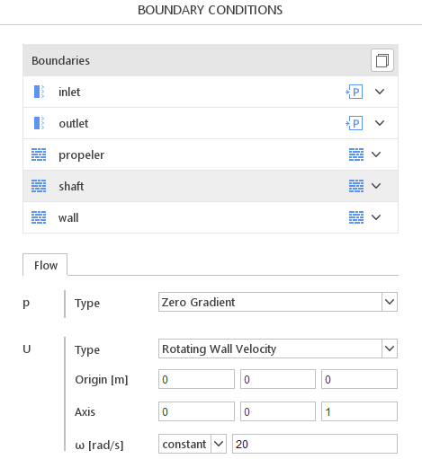
Origin, axis and rotational speed must be defined:
Origin - center of the coordinate system
Axis - axis of the coordinate system
\(\omega\) - rotational speed [rad/s]
Keep in mind that \(\omega\) must be provided in radians per second \([\frac{rad}{s}]\).
Very often instead of \(\omega\) it is more convenient to use rotations per minute RPM. To convert RPM to \([\frac{rad}{s}]\), the following formula must be used:
\(\omega = RPM \cdot \frac{2 \cdot \pi}{60}\)
Rotating Wall Velocity - SimFlow (OpenFOAM) Rotating Wall Velocity - Alternatives
In this section, we propose boundary conditions that are alternative to Rotating Wall Velocity. While they may fulfill similar purposes, they might be better suited for a specific application and provide a better approximation of physical world conditions.
| Boundary Condition | Description |
|---|---|
works similarly to Rotating Wall Velocity, but allows defining wall velocity for translating bodies |