What is Ahmed Body
Flow around the Ahmed body is a well-known CFD benchmark for external aerodynamics. The Ahmed body is a generic car model first proposed by [Ahmed et al., (1984)]. All ground vehicles can be termed as bluff bodies moving close to the road surface. The analyzed body is able to capture the essential features of the flow which characterize modern cars. Most importantly, high-quality test data are available. The aim of the study is to validate results obtained by steady-state, incompressible turbulent flow in SimFlow. We will investigate the flow around the Ahmed body with the slant angle of \(25^o\) and the Reynolds number \(Re = 2,784,000\). Based on the test data, we will validate our simulation model by comparing:
- drag coefficient
- velocity profiles along the Ahmed body
- flow structures behind the body
By validating the model against the test data, we will demonstrate that SimFlow can be applied to the general class of external aerodynamics CFD simulations. For example, SimFlow can be applied to optimization problems of car aerodynamics, which lead to the reduction of drag coefficient and therefore, fuel consumption, \(CO_2\) emissions, and noise.
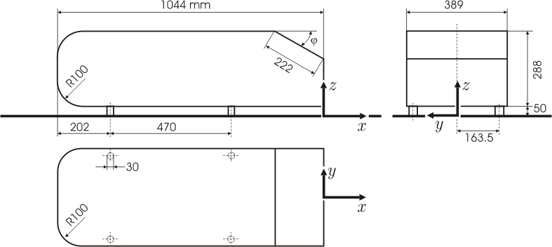
Ahmed Body Dimensions - Geometry
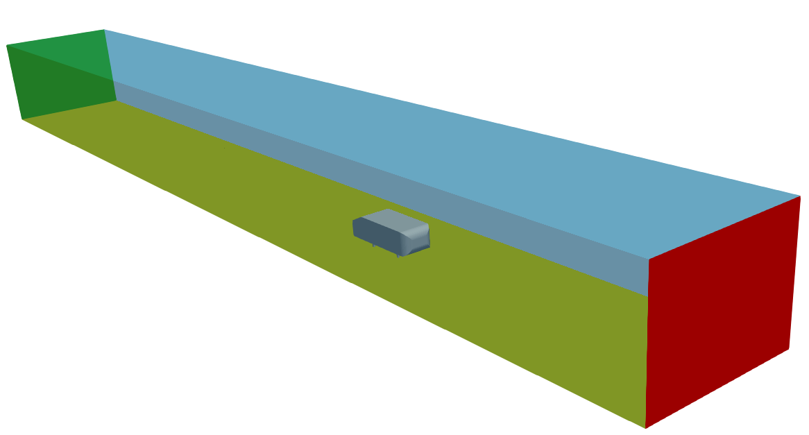
The geometry was prepared based on Ahmed et al. (1984), and the sketch is given in Figure 1. The slant angle \(\phi\) is set to \(25^o\). The body is placed inside the wind tunnel of the dimensions:
15 x 1.4 x 1.87 m in X, Y and Z directions, respectively - Figure 2.
The Ahmed body is located inside the wind tunnel with five times its length in front and ten times its length behind the reference point. The cross-sectional area of the Ahmed body in the X direction is \(0.112 \; m^2\), which will be used for calculation of the drag coefficient.
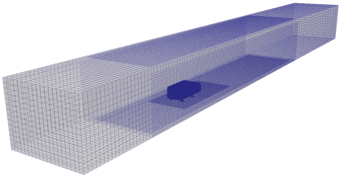
Ahmed Body Mesh
A hex-dominated mesh was created using snappyHexMesh application which is an integral part of SimFlow. The size of the background mesh was chosen in such a way to reflect the dimensions of the wind tunnel. The background mesh cell size was set to 0.1m in each direction.
Refinement regions were applied around the Ahmed body to control the refinement level and smooth transition from highly dense mesh regions to less dense regions.
The boundary layer mesh was created based on relative cell size, with 4 cells in the layer.
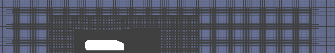
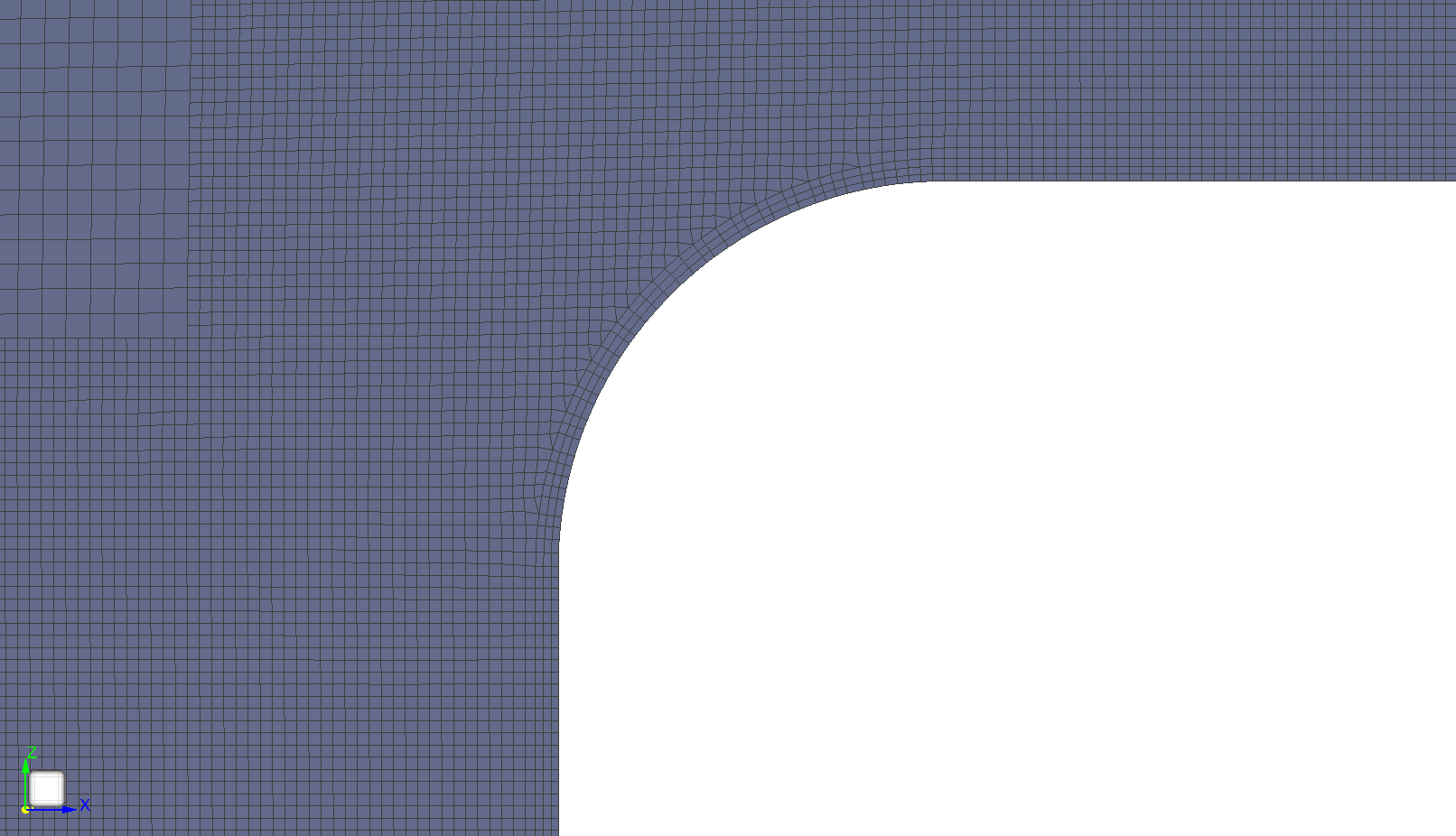
The mesh size was determined based on \(y^+\) - the dimensionless distance from the wall. The goal was to keep \(y^+\) in range \(30 \leq y^+ \leq 300\) so that \(k{-}\omega \; SST\) turbulence model with the Standard Wall Function could be used.
In total, the mesh contains around 16.6M cells.
Ahmed Body Simulation Setup
Steady-state, incompressible simulation was conducted in SimFlow. The incompressible solver simpleFoam is using the Semi-Implicit Method for Pressure Linked Equations (SIMPLE) algorithm for solving flow equations.
The material used for the simulation is air with kinematic viscosity \(\nu = 1.5 \cdot 10^{-5} \; [\frac{m^2}{s}]\).
\(k{-}\omega \; SST\) turbulence model was chosen with Standard Wall Function (\(30 \leq y^+ \leq 300\)).
Boundary conditions are summarized in the table below:
| Parameter | Inlet | Outlet | Road | Ahmed body | Top | Sides |
|---|---|---|---|---|---|---|
Velocity | \(40 \; [\frac{m}{s}]\) | Zero Gradient | No-slip condition | No-slip condition | Symmetry | Symmetry |
Pressure | Zero Gradient | \(0 \; [Pa]\) | Zero Gradient | Zero Gradient | Symmetry | Symmetry |
k | \(0.24 \; [\frac{J}{kg}]\) | Zero gradient | Standard Wall Function | Standard Wall Function | Symmetry | Symmetry |
\(\omega\) | \(16000 \; [\frac{1}{s}]\) | Zero gradient | Standard Wall Function | Standard Wall Function | Symmetry | Symmetry |
Reynolds number is based on the length of the Ahmed body (1.044 m) and equals 2 784 000. Velocity convective part of the equation was discretized using a second-order upwind scheme.
Ahmed Body Simulation Results - Drag & Lift Coefficient
Table 1 presents drag Cd and lift Cl coefficients measured in the test and in CFD simulation. The drag coefficient is a dimensionless quantity that expresses the resistance of the body in a fluid environment during motion. SimFlow prediction of Cd is in a very good agreement with test data (error of 4.6%). Similarly, the drag coefficient is predicted correctly, giving the error of 3.2% compared to test data.
| Parameter | Experiment (Meile et al., 2011) | Simulation |
|---|---|---|
Drag coefficient Cd | 0.299 | 0.313 |
Lift coefficient Cl | 0.345 | 0.355 |
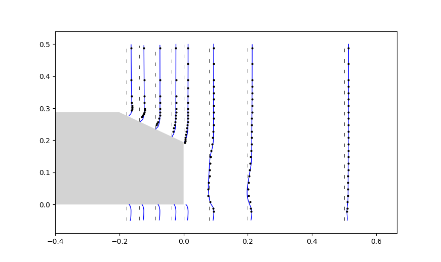
Since the slant angle has a significant influence on the flow behavior, as an additional validation of our model, we will focus on the flow over the slant and the near wake region. Figure 6 presents the profiles of velocity measured in the test and obtained in SimFlow. Test data (velocity profiles) are taken from [ERCOFTAC Test Data AC1-05]. Velocity profiles were measured at the center-line of the Ahmed body and specified locations along the X direction:
x=-178 mm, x=-138 mm, x=-88 mm, x=-38 mm, x=0 mm, x=80 mm, x=200 mm and x=500 mm.
The X component of velocity is plotted. Simulation results show very good agreement with the experimental data.
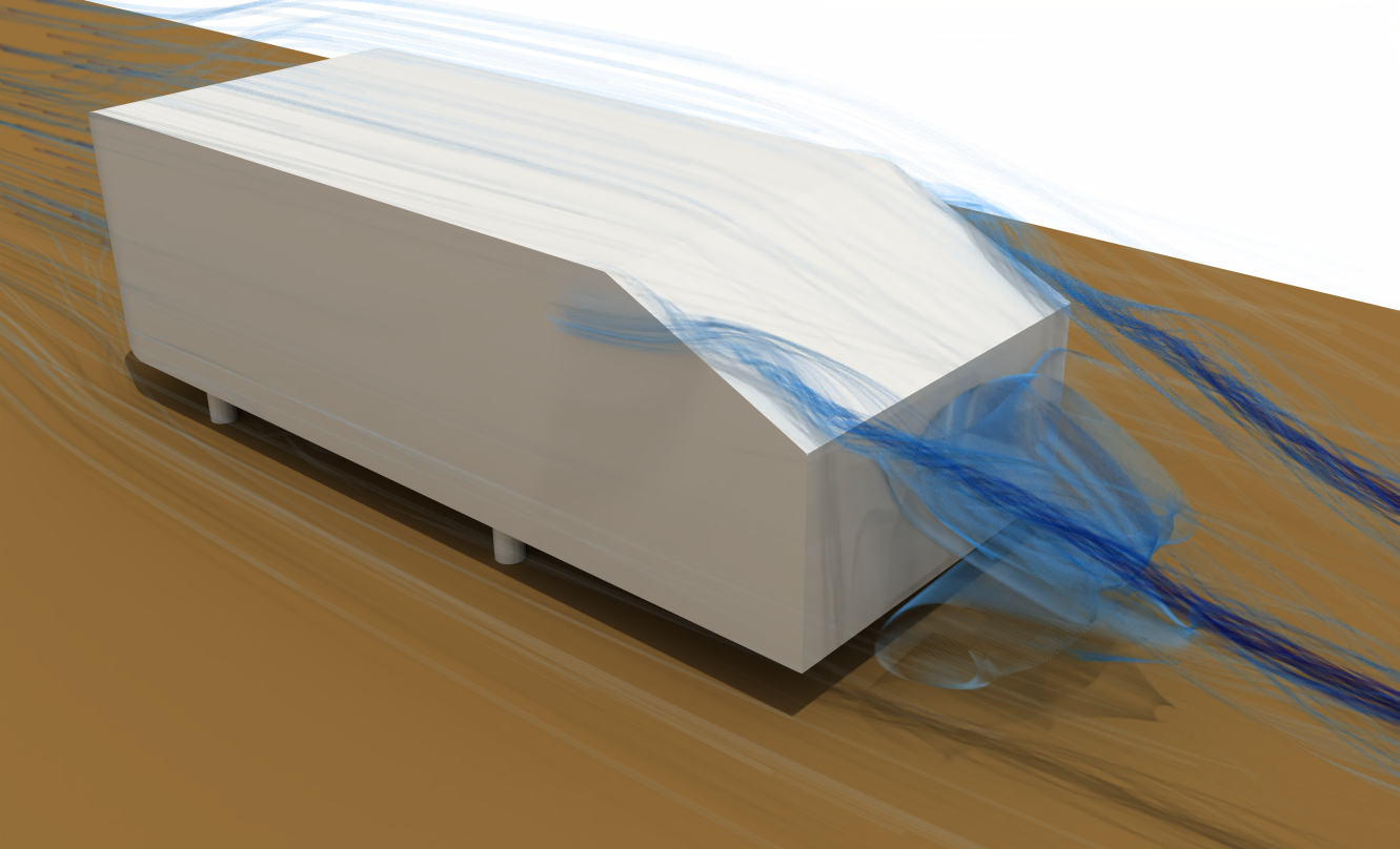
[Ahmed et al., (1984)] described the general wake structure behind the Ahmed body - Figure 7. The characteristic feature is the presence of two recirculation areas marked as regions A and B, situated one over another. It was also noted that those A and B regions do not go to the base surface ("road"), so they are two vortices placed in the so-called "separation bubble" marked by region D. Another characteristic wake structure is the shear layer, coming off the slant side edge, rolls up into a longitudinal vortex - region C. The same structures as indicated in Figure 7 are observed in the simulation results - see Figure 8.
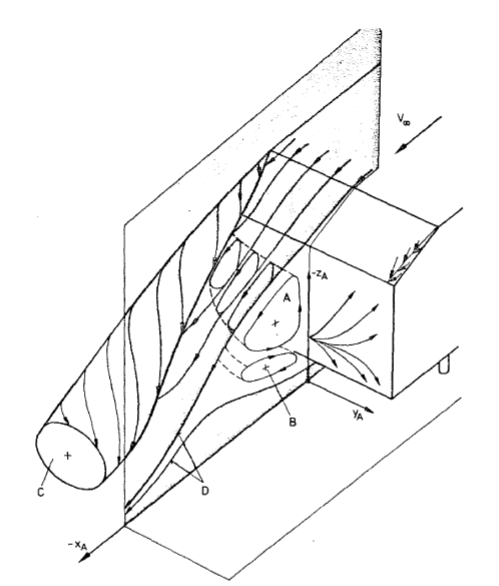
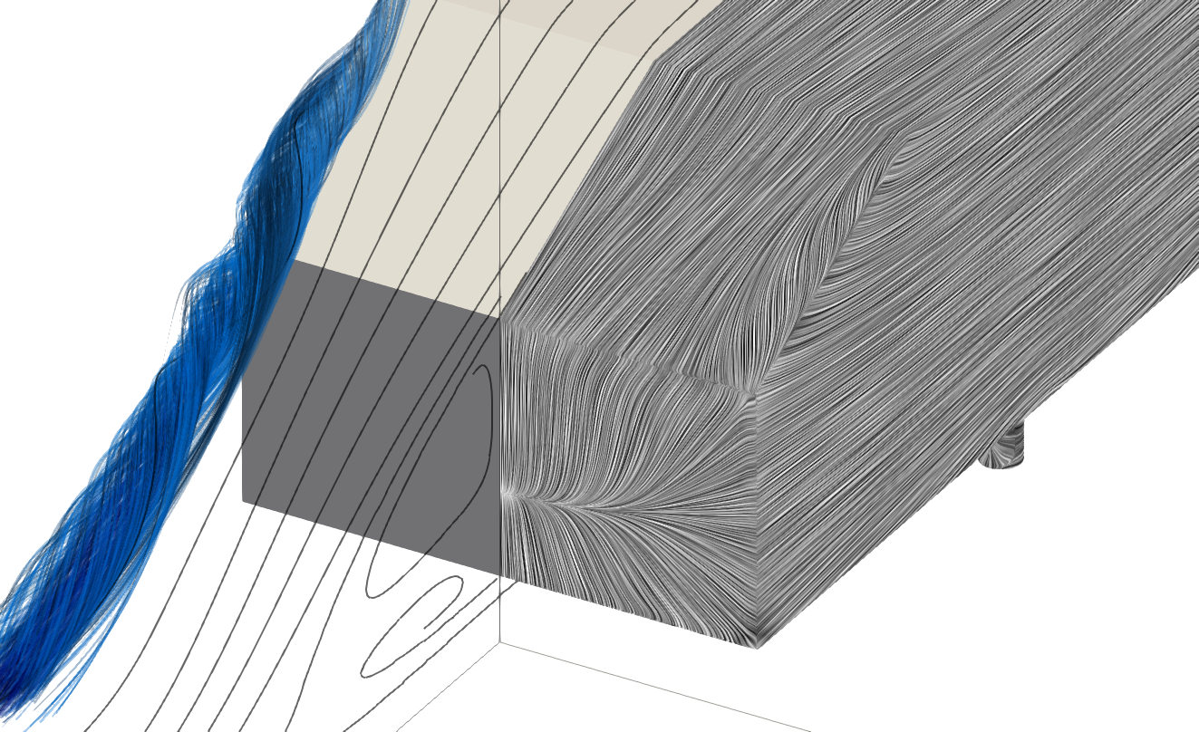
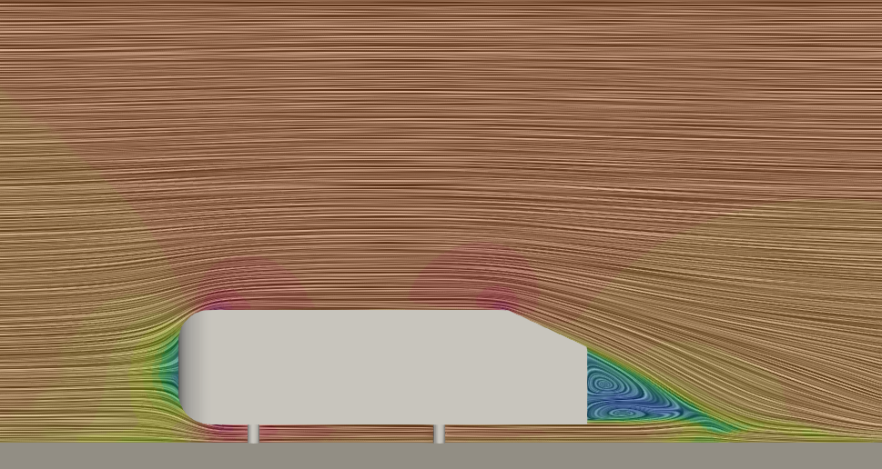
Figure 9 depicts the velocity contours through the mid-center plane of the Ahmed body. Contours reveal that the flow remains attached over the slant, creating the two vortices directly behind the Ahmed body.
Ahmed Body CFD Benchmark Conclusions
The flow around the Ahmed body is a well-known benchmark for CFD solvers. It has been shown that SimFlow is able to provide high-quality results that match the test data in terms of drag coefficient, velocity profiles, and 3D wake structures.
SimFlow predicted the drag coefficient to be Cd=0.313 which matches the test results - Cd=0.299. The difference is at the level of 4.6%. Good agreement was also achieved for lift coefficient Cl=0.345 in test versus Cl=0.355 in simulation, giving the error of 3.2%.
SimFlow was also capable of correctly predicting the flow structures behind the Ahmed body, which was verified with the proposed by Ahmed et al., 1984 wake structure.
SimFlow is a tool that is able to predict the aerodynamics of ground vehicles.
Literature
- [Ahmed et al., (1984)] S.R. Ahmed, G. Ramm and G. Faltin, Some Salient Features of the Time-Averaged Ground Vehicle Wake, SAE Technical Paper 840300, 1984
- [CFD Online] https://www.cfd-online.com/Wiki/Ahmed_body
- [Meile et al., (2011)] W. Meile, G. Brenn, A. Reppenhagen, B. Lechner, A. Fuchs, Experiments and numerical simulations on the aerodynamics of the Ahmed body, CFD Letters 3(1), 2011
- [ERCOFTAC Test Data AC1-05] ERCOFTAC test data, https://www.kbwiki.ercoftac.org/w/index.php?title=Test_Data_AC1-05