Introduction
In this article we will validate SimFlow against a wave impact problem in a rectangular narrow tank as proposed by [SPHERIC Community]. The time history of the motion of the tank as well as the pressure measured at the given locations are provided. By comparing the pressure values from SimFlow we are able to demonstrate the high accuracy of our CFD software in predicting the sloshing phenomena. In the article by [SPHERIC Problem] water and oil fluids were considered. Here, we only limit our study to water, but because of the high Reynolds number (97546), the flow is turbulent, which is more challenging than the case with oil (the Reynolds number of 1748 - resulting in the laminar case).
Definition of the experiment
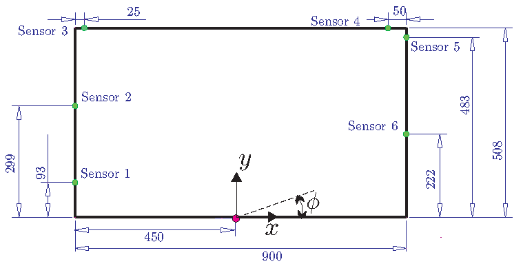
The geometry of the tank is shown in Figure 1. The thickness of the tank in z direction is 62mm. But the setup allows changing the tank thickness to 31mm and 124mm in order to study 2D and 3D effects. In our investigation we only considered the test case with baseline thickness of 62mm. The water level was 93mm, which corresponds to Sensor 1 location. The tank can rotate around the z axis, around the central point marked with the red dot in Figure 1. The roll angle history change is given to replicate the tank motion. Additionally, the videos and pressure measurements from the test series are provided by [SPHERIC Problem]. This test case focuses on the impact event, which is the first pressure peak. The physical properties of water are given in the Table 1.
\(\rho\) for density, \(\mu\) for the dynamic viscosity, \(\nu\) for the kinematic viscosity, \(\sigma\) for surface tension
| \(\rho[{kg}/m^3]\) | \(\nu [m^2/s]\) | \(\nu [Pa\ \cdot s]\) | \(\sigma [N/m]\) |
|---|---|---|---|
998 | \(1.0 \cdot 10^{-6}\) | \(1.0 \cdot 10^{-3}\) | 0.0728 |
Numerical model
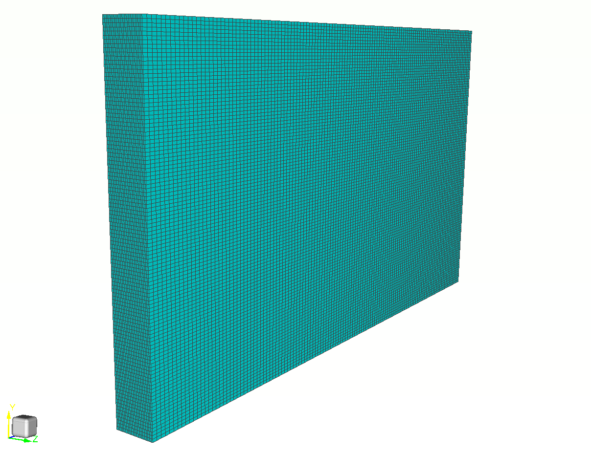
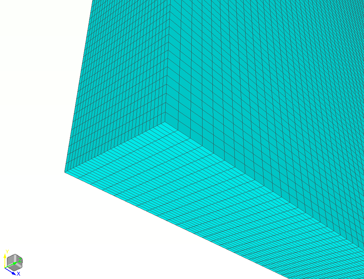
The numerical domain is a box with dimensions corresponding to the tank geometry. The hex mesh was created by means of blockMesh utility which is integrated to SimFlow. The mesh is presented in Figure 2 and Figure 3. The total number of elements used in this study equals 396 000.
Mesh convergence studies were conducted to examine the optimum mesh size. Additionally, numerical set-up of the model was also investigated.
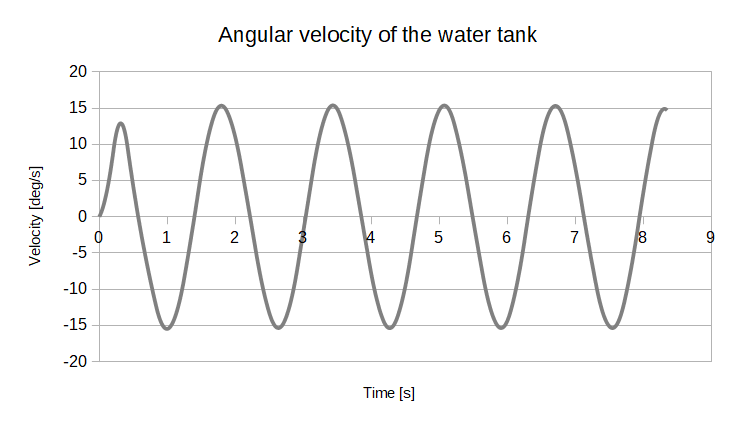
The motion of the tank was defined by means of dynamic mesh capabilities of SimFlow. The rotation around the z axis was defined, and the angular velocity defined based on the test data provided by [SPHERIC Benchmark Data].
Pressure sensor was realized by means of a moving probe which followed the motion of the dynamic mesh.
The boundary conditions are set to wall for all boundaries of the domain. The rotational mesh motion was defined according to the test data, which is shown in Figure 4.
Results
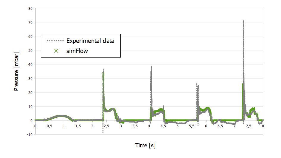
The pressure measurements from the test are compared to SimFlow results in Figure 5. Several observations should be made. Firstly, the timing of each pressure peak is captured perfectly by SimFlow. In further part of this article we will additionally plot pictures from the test and simulation to show the water movement in the tank. Secondly, the pressure value for the first peak is captured very well. For the second to fourth peak, we can observe a small deviation from the experimental data. However, the difference is relatively small. Moreover, during the mesh convergence studies, it was observed that the difference becomes smaller with further mesh refinement. For this study the optimum mesh size was chosen to provide accurate results in a relatively short period of time.
Below we present the movie that compares the motion of the tank in the test versus simulation results for the 8s of the motion. It should be noted that the dynamics of the water is captured accurately together with the shape of the waves that are created in the tank.
Summary
SimFlow was used to perform multiphase simulation based on the lateral water tank test carried out by [SPHERIC Community]. The high accuracy of SimFlow was proved by capturing water movement inside the tank. Comparison of pressure measurements of the test with numerical predictions are very close to each other.
Multiphase simulations including two or more phases are often found in different branches of industry, including: automotive, power generation, chemical industry, food industry, environment, and even medicine (blood flow). With proven high accuracy of SimFlow, the CFD software can be an inestimable tool in the development process, resulting in cost reduction and focusing on best performance of the final products.
Literature
- [Botia-Vera et al.] Botia-Vera, E, Souto-Iglesias, A., Bulian, G. & Lobovsky, L., "Three SPH Novel Benchmark Test Cases for free surface flows"
- [SPHERIC Problem] Sloshing Wave impact problem: https://spheric-sph.org/tests/test-10
- [SPHERIC Benchmark Data] Benchmark Data: http://canal.etsin.upm.es/ftp/SPHERIC_BENCHMARKS/
- [SPHERIC Community] https://spheric-sph.org/